|
|
|
|
|
 
|
글쓴이 :
피앤에스
 조회 : 3,805 |
|
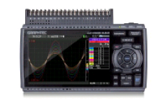
[midi 로거]
휴대용 데이터로거
모델명 :
GL840
|
|
- "고전압" 모델과 "표준" 모델 2가지 제품 구성
- 3종류의 입력 방식(Logic/Pulse, 아날로그 신호, 디지털 센서)
- 무선 LAN 유닛으로 Wireless 계측
- GL100과 연결 가능
- 최고 10ms 샘플링 속도
- 4GB 메모리로 장시간 수록 가능
|
Withstand voltage & Accuracy |
GL-840M |
GL840WV |
|
Multi-input type (B-564) |
Withstand-voltage type (B-565) |
|
Voltage |
Input voltage range |
20 mV to 100 V |
20 mV to 100 V |
|
Max. voltage (Input - GND) |
60 Vp-p |
300 Vp-p |
|
Temp. |
Thermocouple |
R, S, B, K, E, T, J, N, W (WRe5-26) |
|
RTD (Resistance Temp. Detector) |
Pt100 (IEC751), Pt1000 (IEC751), JPt100 (JIS) |
|
Accuracy |
Voltage |
± 0.1% of F.S. |
± (0.05% of FS + 10μV) |
|
Temperature* |
± 1.55 ºC |
± 1.1 ºC |
3종류의 입력 방식으로 다양한 측정이 가능
입력 1 : 최대 200ch 확장 가능! 아날로그 입력 포트 (절연 Multi-Function 입력)
아날로그 신호 입력용으로 표준 입력 Terminal(B-564)과 고전압 Terminal(B-565)를 사용하여 측정 용도에 따른 Terminal을 사용할 수 있습니다.
두 Terminal 모두 전 채널 절연 입력 방식을 채용하여 다양한 측정이 가능합니다.
표준 채널 수가 20ch, 최대 200ch까지 확장이 가능하며, 연결 케이블, 확장 베이스, Terminal을 사용하면 최대 20m까지 본체 및 Terminal을 연장할 수 있습니다.

아날로그 신호 입력 포트의 채널 확장
Terminal Base 채널 수는 표준 20ch부터 최대 200ch까지 20ch씩 확장이 가능합니다.
- GL840-M에서의 확장 예


GL840용 확장 Terminal 연결 케이블 (50cm, 2m의 2종류)를 사용하여 본체-Terminal 간 또는, Terminal-Terminal 을 연결할 수 있습니다.
* 노이즈의 영향이 있는 경우에는 샘플링 속도를 늦춰주시길 바랍니다.

입력 2 : 디지털 센서 연결 포트
GL100의 7종류의 센서와 Terminal / adaptor 연결하여 계측의 폭을 더욱 넓힐 수 있습니다.


|
GS센서・단자/어댑터 최고 샘플링 속도는 500ms입니다. GL840이 500ms보다 빠른 설정을 했을 때에는,
GS센서・단자/어댑터 데이터로서 500ms마다 데이터가 갱신되어 갱신될 때까지는 같은 데이터가 계속됩니다. | | |
입력 3 : Logic/Pulse 포트
Logic 또는 Pulse 신호를 선택하여 4ch 입력 가능합니다.
최고 샘플링 속도 10ms
채널 수를 줄여 최고 10ms로 데이터 수록이 가능합니다.

4GB 메모리로 장시간 수록 가능
4GB의 플래시 메모리를 탑재하였습니다. 수록 데이터는 GBD 형식과 CSV 형식으로 보존이 가능합니다.
수록 시간 예 (아날로그 20ch만 사용시, 2GB 수록 시)

* 수록 시간은 대략적으로 계산한 것입니다. 샘플링 속도에 따라서 ch수에 제한이 있습니다. 10ms : 1ch, 50ms : 5ch, 100ms : 10ch
Ring 수록 기능
설정한 수록점 수를 넘어가면 오래된 데이터를 삭제하고 새로운 데이터를 기록합니다.
설정 가능 점 수 : 1000점 ~ 2,000,000점
Relay 수록 기능
GL840의 1회 데이터 수록 용량은 2GB입니다.
위 기능을 사용하여 데이터를 제거하지 않고 2GB 단위로 파일을 잘라 연속 수록이 가능합니다.
수록 중 SD 카드 교환 기능

데이터 수록 중에 SD 카드의 교환이 가능합니다.
편리한 기능
알람 출력 기능

이상 신호 발생시, 알람 신호를 출력합니다.
각 채널에서 조건 설정이 가능합니다.
출력은 4출력이 가능합니다.
USB 드라이브 모드
GL840과 PC를 USB 케이블로 연결하여 USB 드라이브 모드를 기동하면
GL840이 PC 드라이브의 하나로 인식되어 GL840 내의 측정 파일을 Drag&Drop으로 PC로 옮길 수 있습니다.
네비게이션 기능
초보자를 위한 수록 설정 및 Trigger 설정, 간단한 무선 LAN 설정을 안내합니다.
7인치 TFT 액정
보기 쉽고 조작성이 좋은 7인치 TFT 액정을 사용하였습니다.
3WAY 전원

GL840 전원은 AC 전원, DC, 배터리의 3가지 전원을 사용할 수 있습니다.
네트워크 기능

네트워크를 이용하여 데이터를 주고 받을 수 있습니다.
WEB 브라우저 기능 / FTP 서버 기능
FTP 클라이언트 기능 / NTP 클라이언트 기능
GL840 Main unit specifications
|
Item |
Description |
|
Model number |
GL840-M |
GL840-WV |
|
Number of analog input channels |
20 channels in standard configuration, Expandable up to 200 channels |
|
Number of analog input terminals |
Up to 10 terminals (20 channels / terminal), standard config: 1 |
|
Type of analog input terminal |
Multi-input type, Withstand-voltage type |
|
Port for digital sensor |
1 port for the sensor/input terminal/adapter of the GL100 |
|
External input/
output *1 |
Input *2 |
Trigger or Sampling (1 channel), Logic/Pulse (4 channels) |
|
Output *3 |
Alarm (4 channels) |
|
Sampling interval |
10 ms to 1 hour (10ms to 50ms: voltage only) *4, External signal |
|
Time scale of waveform display |
1 sec. to 24 hour /division |
|
Trigger,
Alarm function |
Trigger action |
Start or stop capturing data by the trigger |
|
Repeat action |
Off, On (auto rearmed) |
|
Trigger source |
Start: Off, Measured signal, Alarm, External, Clock, Week or Time
Stop: Off, Measured signal, Alarm, External, Clock, Week or Time |
|
Condition Setting |
Combination: OR or AND
Analog signal: Rising (High), Falling (Low), Window-in, Window-out
Logic signal: Pattern (combination of each input signal in high or low)
Pulse (number of count): Rising (High), Falling (Low), Window-in, Window-out |
|
Alarm output |
Outputs a signal when alarm condition occurs in the input signal *5 |
|
Pulse input
function |
Rotation count
(RPM) mode |
Counts the number of pulses per sampling interval and converts to rpm
(rotations per minute), Number of pulses for one rotation can be set to
50, 500, 5000, 50k, 500k, 5M, 50M, 500M rpm/F.S. (rpm./Full Scale) |
|
Accumulating
count mode |
Accumulates the number of pulses from the start of measurement
50, 500, 5000, 50k, 500k, 5M, 50M, 500M C/F.S. (Counts/Full Scale) |
|
Instant count
mode |
Counts the number of pulses per sampling interval
50, 500, 5000, 50k, 500k, 5M, 50M, 500M C/F.S. (Counts/Full Scale) |
|
Calculation
function |
Between channels |
Addition, Subtraction, Multiplication, and Division for analog input |
|
Statistical |
Select two calculations from Average, Peak, Maximum, Minimum, RMS |
|
Search function |
Search for analog signal levels, values of logic or pulse or alarm point
in captured data |
|
Interface to PC |
Ethernet (10 BASE-T/100 BASE-TX), USB (Hi-speed), WLAN (using B-568 option) |
|
Storage
device |
Internal |
Built-in 4GB Flash Memory *6 |
|
External |
One SD card slot (Support SDHC memory card, up to 32GB) *7 |
|
Saved contents |
Captured data, Setting conditions, Screen copy |
|
Capturing mode |
Mode: Normal, Ring, Relay
Ring: Saves most recent data (Number of capturing data: 1000 to 2000000 points) *8
Relay: Saves data to multiple files without losing data until dada capturing is stopped |
|
Replay data |
Replays captured data that was saved in the GL840 (in GBD or CSV format) |
|
Scaling (Engineering unit) function |
Measured value can be converted to specified engineering unit
• Analog voltage: Converts using four reference points (gain, offset)
• Temperature: Converts using two reference points (offset)
• Pulse count: Converts using two reference points (gain) |
|
Action during data capture |
• Displaying past data (using dual display mode (Current + Past data))
• Hot-swapping the SD memory card
• Saving data in between cursors |
|
Display |
Size |
7-inch TFT color LCD (WVGA: 800 x 480 dots) |
|
Language |
English, French, German, Chinese, Korean, Russian, Spanish, Japanese |
|
Information *9 |
Waveform in Y-T with digital values, Waveform only, Digital value, Digital values
and statistics values |
|
Operating environment |
0 to 45 ºC, 5 to 85 % RH (non condensed)
(When operating with battery pack 0 to 40 ºC, charging battery 15 to 35 ºC) |
|
Power source |
AC adapter |
100 to 240 V AC, 50/60 Hz (1 pc of adapter is attached as standard accessory) |
|
DC power |
8.5 to 24 V DC (DC drive cable (option B-514) is required) |
|
Battery pack |
Mountable two battery packs (battery pack (option B-569): 7.2V DC, 2900mAh) |
|
Power consumption *10 |
Max. 38 VA |
|
External dimensions (W x D x H
in mm, Excluding projections) |
Approx. 240 x 158 x 52.5 |
Approx. 240 x 166 x 52.5 |
|
Weight *11 |
Approx. 1010 g |
Approx. 1035 g | - *1
- Input/Output cable for GL (option B-513) is required to connect the signal.
- *2
- Input signal;
- Voltage range: Up to 24V (common ground)
- Signal type: Voltage, Open collector, Contact (relay)
- Threshold: Approx. + 2.5 V (Hysteresis: Approx. 0.5V (2.5V to 3V))
- *3
- Output signal: Open collector (pull-up to 5V by 10kΩ resistor)
- Voltage: Max. 30V,
- Current: Max. 0.5A,
- Collector dissipation: Max. 0.2W
- *4
- Minimum interval varies by number of channels used.
- *5
- Output port can be specified in each input channel.
- *6
- The built-in Flash memory is available for units with serial numbers C604XXXX or later. Please contact your local representative for more information.
- *7
- SD memory card cannot be used on the SD card slot while the wireless LAN unit (opton B-568) is used.
- *8
- Size of the capture data will be limited to 1/3 of available memory.
- *9
- Display mode is switched every time the dedicated key is pressed. In magnified digital value mode, the
displayed channel number can be specified. In the waveform display mode, the changing of the time scale will
be effective from the point of the next displayed data. - *10
- Rating under maximum power consumption using the AC adapter, with LCD display on, and battery pack(s)
being charged. - *11
- Excludes AC adapter and battery pack.
Software specifications for PC
|
Item |
Description |
|
Model name |
GL100_240_840-APS |
|
Supported OS |
Windows 10, 8.1, 8, 7, Vista (32/64-bit edition) |
|
Supported device |
GL840 (USB, Ethernet, WLAN), GL100 (USB, WLAN) |
|
Functions |
Control the GL series, Real-time data capture, Replay data, and Data format conversion |
|
Supported units & channels |
Up to 1000 channels total, Up to 4 groups (number of units is limited by model) |
|
Settings control |
Input condition, Capturing condition, Trigger/Alarm condition, Report, etc. |
|
Capturing data |
Saved to PC |
Saves captured data in real time (in GBD binary or CSV format) |
|
Saved to GL unit |
Saves to the SD memory card (in GBD binary or CSV format) |
|
Displayed information |
Y-T waveform, Digital values, Report, X-Y graph (specified period of data, data
reply only), Two displays for the current and past data, and Statistical calculation |
|
File operation |
Converting data format to CSV from GBD binary, merge multiple data files
in the time axis or as an additional channel |
|
Warning function |
Send e-mail to the specified address when the alarms occur |
|
Statistical calculation |
Maximum, Minimum, and Avarage during data capturing |
|
Report function |
Creates the daily or monthly report automatically |
Software specifications for Smart device
|
Item |
Description |
|
Model name |
GL-Connect |
|
Supported OS |
Android 4.1 to 6.0, iOS 7/8/9 (up to 9.3.4) |
|
Supported device |
GL840 (WLAN), GL100 (WLAN) |
|
Functions |
Control the GL series, Display measured data in waveform or digital value |
|
Supported units |
Up to 10 units |
|
Settings control |
Start/Stop, Sampling interval |
|
Capturing data |
Saves captured data in the GL main body (data cannot be saved in the smart device) |
|
Displayed information |
Data captured in real time by digital value, Replay the data stored in the GL body by the waveform |
Wireless LAN unit (option) specifications
|
Item |
Description |
|
Model number |
B-568 |
|
Supported device |
GL840 |
|
Communication method |
Wireless communication (using radio waves in the 2.4GHz band) |
|
Supported WLAN system |
IEEE802.11b/g/n
WPS: Push button or PIN method
Security protocols: WEP64, WEP128, WPA-PSK/WPA2-PSK, AKIP/AES
Communication distance: Approx. 40m (depending on the conditions of radio
communication) |
|
Installed location |
Attaches to the SD card slot *7 |
|
Function |
Access Point mode: Communicate with the GL100-WL as a remote sensor
(captured data in the GL100-WL is transferred to GL840)
Station mode: Communicate with PC or Smart device (control GL840 and
transfer the data from GL840) |
|
Connected number of GL100-WL |
GL840: Up to 5 units of the GL100-WL |
GL840 Analog input specifications
|
Item |
Description |
|
Model number |
GL840-M, Input terminal B-564 |
GL840-WV, Input terminal B-565 |
|
Input method |
All channels isolated balanced input *12, Scans channels for sampling |
|
Type of input terminal |
Screw terminal (M3 screw) |
|
Measurement
range |
Voltage |
20, 50, 100, 200, 500 mV, 1, 2, 5, 10, 20, 50, 100 V, and 1-5V F.S. (Full Scale) |
|
Thermocouple |
Type: K, J, E, T, R, S, B, N, W (WRe5-26)
Range: 100, 500, 2000 ºC *13 |
|
RTD (Resistance
Temperature Detector) |
Type: Pt100, Pt1000 (IEC751), JPt100 (JIS)
Range: 100, 500, 2000 ºC *13 |
|
Humidity |
0 to 100 % RH - using the humidity sensor (option B-530) |
|
Filter |
Off, 2, 5, 10, 20, 40 (moving average in selected number) |
|
Measurement accuracy *14 |
|
Voltage |
± 0.1% of F.S. (Full Scale) |
± (0.05% of F.S. + 10μV) |
|
Temperature (Thermocouple) *15 |
|
|
Type |
Measurement range
(TS: Temp Sense) |
Measurement accuracy |
Measurement accuracy |
|
R |
0 ≤ TS ≤ 100 ºC |
± 5.2 ºC |
± 4.5 ºC |
|
100 < TS ≤ 300 ºC |
± 3.0 ºC |
± 3.0 ºC |
|
300 < TS ≤ 1600 ºC |
± (0.05% of rdg. + 2.0 ºC) |
± 2.2 ºC |
|
S |
0 ≤ TS ≤ 100 ºC |
± 5.2 ºC |
± 4.5 ºC |
|
100 < TS ≤ 300 ºC |
± 3.0 ºC |
± 3.0 ºC |
|
300 < TS ≤ 1760 ºC |
± (0.05% of rdg. + 2.0 ºC) |
± 2.2 ºC |
|
B |
400 ≤ TS ≤ 600 ºC |
± 3.5 ºC |
± 3.5 ºC |
|
600 < TS ≤ 1820 ºC |
± (0.05% of rdg. + 2.0 ºC) |
± 2.5 ºC |
|
K |
-200 ≤ TS ≤ -100 ºC |
± (0.05% of rdg. + 2.0 ºC) |
± 1.5 ºC |
|
-100 < TS ≤ 1370 ºC |
± (0.05% of rdg. + 1.0 ºC) |
± 0.8 ºC |
|
E |
-200 ≤ TS ≤ -100 ºC |
± (0.05% of rdg. + 2.0 ºC) |
± 1.0 ºC |
|
-100 < TS ≤ 800 ºC |
± (0.05% of rdg. + 1.0 ºC) |
± 0.8 ºC |
|
T |
-200 ≤ TS ≤ -100 ºC |
± (0.1% of rdg. + 1.5 ºC) |
± 1.5 ºC |
|
-100 < TS ≤ 400 ºC |
± (0.1% of rdg. + 0.5 ºC) |
± 0.6 ºC |
|
J |
-200 ≤ TS ≤ -100 ºC |
± 2.7 ºC |
± 1.0 ºC |
|
-100 < TS ≤ 100 ºC |
± 1.7 ºC |
± 0.8 ºC |
|
100 < TS ≤ 1100 ºC |
± (0.05% of rdg. + 1.0 ºC) |
± 0.6 ºC |
|
N |
-200 ≤ TS < 0 ºC |
± (0.1% of rdg. + 2.0 ºC) |
± 2.2 ºC |
|
0 ≤ TS ≤ 1300 ºC |
± (0.1% of rdg. + 1.0 ºC) |
± 1.0 ºC |
|
W |
0 ≤ TS ≤ 2000 ºC |
± (0.1% of rdg. + 1.5 ºC) |
± 1.8 ºC |
|
R.J.C. |
± 0.5 ºC |
± 0.3 ºC |
|
Temperature (RTD) *16 |
|
|
Type |
Measurement range
(TS: Temp Sense) |
Accuracy |
Accuracy |
|
Pt100 |
-200 ≤ TS ≤ 100 ºC |
± 1.0 ºC |
± 0.6 ºC |
|
100 < TS ≤ 500 ºC |
± 0.8 ºC |
|
500 < TS ≤ 850 ºC |
± 1.0 ºC |
|
Pt1000 |
-200 ≤ TS ≤ 100 ºC |
± 0.8 ºC |
± 0.6 ºC |
|
100 < TS ≤ 500 ºC |
± 0.8 ºC |
|
JPt100 |
-200 ≤ TS ≤ 100 ºC |
± 0.8 ºC |
± 0.6 ºC |
|
100 < TS ≤ 500 ºC |
± 0.8 ºC |
|
A/D converter |
Sigma-Delta type, 16 bits (effective resolution: 1/40000 of the measuring full range) |
|
Input resistance |
1MΩ ±5% |
|
Allowable signal source resistance |
Up to 300Ω |
Up to 100Ω |
|
Maximum
input voltage |
Between
(+) / (-) terminal |
20 mV to 2 V range: 60 Vp-p,
5 V to 100 V range: 110 Vp-p |
|
Channels ((-) / (-)) |
60 Vp-p |
600 Vp-p |
|
Channel / GND |
60 Vp-p |
300 Vp-p |
|
Max. voltage
(withstand) |
Between channels |
350 Vp-p (1 minute) |
600 Vp-p |
|
Channel / GND |
350 Vp-p (1 minute) |
2300 Vrms AC (1 minute) | - *12
- The terminal "b" for using the RTD is connected each other across all channels.
- *13
- If the specifications of the temperature sensor is lesser or greater than the selected measurement range, GL840
can measure up to the specifications of the sensor. - *14
- Subject to the following conditions:
- Room temperature is 23 oC ± 5 oC.
- When 30 minutes or more have elapsed after power has turned on.
- Filter is set to 10.
- Sampling rate is set to 1 sec, using 20-channel in GL840-M and 10-channel in GL840-WV.
- GND terminal is connected to ground.
- *15
- Wire size of thermocouple used is 0.32mm diameter in the T or K type and 0.65mm diameter in other types.
- *16
- Supports 3-wire type sensor.
Options and Accessories<
|
Item |
Model number |
Description |
|
Input terminal (Multi-inputs) |
B-564 |
20ch input terminal, multi-input type |
|
Input terminal (Withstand voltage |
B-565 |
| |
|
|
|