Key Features��
- Unique LED mode for LED power driver test
- Programmable LED dynamic resistance (Rd)
- Programmable internal resistance (Rr) for simulating LED ripple current
- Fast response for PWM dimming test
- Up to eight channels in one mainframe
- 16-bit precision voltage and current measurement with dual-range
- Full Protection: OC, OP, OT protection and OV alarm
<iframe src="http://www.youtube.com/embed/QGXa2Y6t3Pw?hl=zh&fs=1" frameborder="0" width="560" height="345" style="padding: 0px; margin: 0px; border: 0px"></iframe>
As a constant current source, the LED driver has an output voltage range with a constant output current. LED drivers are usually tested in one of the following ways:
- With LEDs
- Using resistors for loading
- Using Electronic Loads in Constant Resistance (CR) mode, or Constant Voltage (CV) mode
However all these testing methods each have their own disadvantages.
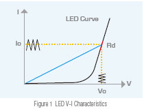
As shown on the V-I curve in figure 1, the LED has a forward voltage VF and a operating
resistance (Rd). When using a resistor as loading, the V-I curve of the resistor is not able to
simulate the V-I curve of the LED as shown in blue on figure 1. This may cause the LED driver
to not start up due to the difference in V-I characteristic between the resistors and the LEDs.
When using Electronic Loads, the CR and CV mode settings are set for when the LED is
under stable operation and therefore, is unable to simulate turn on or PWM brightness control
characteristics. This may cause the LED driver to function improperly or trigger it��s protection
circuits. These testing requirements can be achieved when using a LEDs as a load; however,
issues regarding the LED aging as well as different LED drivers may require different types of
LEDs or a number of LEDs. This makes it inconvenient for mass production testing.
Chroma has created the industries first LED operating mode for simulating LED loading with our 63110A load model from our 6310A series Electronic Loads. By setting the LED driver's output voltage, and current, the Electronic Load can simulate the LED��s loading characteristics. The LED��s forward voltage and operating resistance can also be set to further adjust the loading current and ripple current to better simulate LED characteristics. The 63110A design also has increased bandwidth to allow for PWM dimming testing.
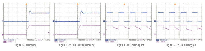
Figure 2 shows the current waveform from a LED load. Figure 3 shows the current waveform from 63110A's LED mode load function. From figures 2 and 3, the start up voltage and current of the LED driver is very similar. Figure 4 shows the dimming current waveform of the LED. Figure 5 shows the dimming current waveform when using 63110A as a load.
The internal resistance (Rr) can be adjusted to simulate the LED driver output ripple current. The traditional E-load can not simulate the ripple current of LED shown as Figure 6. Figure 7 shows the ripple current waveform from a LED load. Figure 8 shows the ripple current waveform from the 63110A LED mode load function.
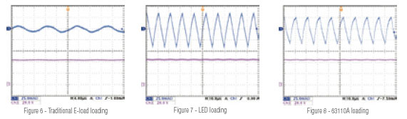
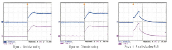
Figure 9 shows the current waveform from a resistive load. Figure 10 shows the current waveform from a CR mode of an Electronic Load loading. Figure 9 and 10 current waveform differs significantly from that of LED loading, especially the voltage and current overshoot, which may cause the LED driver to go into protection. Using resistive load or CR mode to test LED drivers may cause the LED drivers to fail to turn on as shown in Figure 11.
<iframe src="http://www.youtube.com/embed/QGXa2Y6t3Pw?hl=zh&fs=1" frameborder="0" width="560" height="345" style="padding: 0px; margin: 0px; border: 0px"></iframe>
As a constant current source, the LED driver has an output voltage range with a constant output current. LED drivers are usually tested in one of the following ways:
- With LEDs
- Using resistors for loading
- Using Electronic Loads in Constant Resistance (CR) mode, or Constant Voltage (CV) mode
However all these testing methods each have their own disadvantages.
As shown on the V-I curve in figure 1, the LED has a forward voltage VF and a operating
resistance (Rd). When using a resistor as loading, the V-I curve of the resistor is not able to
simulate the V-I curve of the LED as shown in blue on figure 1. This may cause the LED driver
to not start up due to the difference in V-I characteristic between the resistors and the LEDs.
When using Electronic Loads, the CR and CV mode settings are set for when the LED is
under stable operation and therefore, is unable to simulate turn on or PWM brightness control
characteristics. This may cause the LED driver to function improperly or trigger it��s protection
circuits. These testing requirements can be achieved when using a LEDs as a load; however,
issues regarding the LED aging as well as different LED drivers may require different types of
LEDs or a number of LEDs. This makes it inconvenient for mass production testing.
Chroma has created the industries first LED operating mode for simulating LED loading with our 63110A load model from our 6310A series Electronic Loads. By setting the LED driver's output voltage, and current, the Electronic Load can simulate the LED��s loading characteristics. The LED��s forward voltage and operating resistance can also be set to further adjust the loading current and ripple current to better simulate LED characteristics. The 63110A design also has increased bandwidth to allow for PWM dimming testing.
Figure 2 shows the current waveform from a LED load. Figure 3 shows the current waveform from 63110A's LED mode load function. From figures 2 and 3, the start up voltage and current of the LED driver is very similar. Figure 4 shows the dimming current waveform of the LED. Figure 5 shows the dimming current waveform when using 63110A as a load.
The internal resistance (Rr) can be adjusted to simulate the LED driver output ripple current. The traditional E-load can not simulate the ripple current of LED shown as Figure 6. Figure 7 shows the ripple current waveform from a LED load. Figure 8 shows the ripple current waveform from the 63110A LED mode load function.
Figure 9 shows the current waveform from a resistive load. Figure 10 shows the current waveform from a CR mode of an Electronic Load loading. Figure 9 and 10 current waveform differs significantly from that of LED loading, especially the voltage and current overshoot, which may cause the LED driver to go into protection. Using resistive load or CR mode to test LED drivers may cause the LED drivers to fail to turn on as shown in Figure 11.